Today I tried to send a 12-bit number to my Arduino board, in which each bit controls a digital output connected to a LED.
Test completed. Mission accomplished! Once I have my MAX7219 IC, I will try to control 64 LEDs… which will be useful for my annunciator panel later on.
/*
Test reading 12-character input from serial port.
Reads 12 characters from the serial port to control a series of leds that represent annunciator status fields of the KA350i.
The final implementation will use a MAX7219ENG (DIP) serially interfaced 8-digit LED display driver to control a 8x8 LED matrix, but the idea will be more or less the same.
Each character represents the status of LED: 0=OFF, 1=ON.
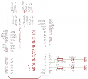
This test will only light up 2 LEDS (see circuit).
e.g.
111111111111 lights up all LEDs
010100000000 lights up the 2nd and the 4th LED
000000000000 shut off all LEDs
The circuit:
- LED 1 (RED) to digital pin 2, with 220 Ohm resistor
- LED 2 (GREEN) to digital pin 4, with 220 Ohm resistor
Created 2016/01/29
By Maarten Van Damme
Modified
By Maarten Van Damme
http://projects.familievandamme.be
*/
char buffer[13];//One character bigger than the intended number of characters.
int received;
int redLed = 2;
int greenLed = 4;
void setup() {
received = 0;
buffer[received] = '\0';
Serial.setTimeout(200);
Serial.begin(9600);
pinMode(redLed, OUTPUT);
pinMode(greenLed, OUTPUT);
}
void loop() {
if (Serial.available())
{
buffer[received++] = Serial.read();
buffer[received] = '\0';
if (received >= (sizeof(buffer) - 1))
{
int myInt = atoi(buffer);
Serial.println(buffer);
received = 0;
for (int i = 0; i < sizeof(buffer) - 1; i++)
{
Serial.print("LED: ");
Serial.print(i+1);
Serial.print(": ");
Serial.print(buffer[i]);
(buffer[i]=='1' ? Serial.println(" --> ON") : Serial.println(" --> OFF"));
digitalWrite(i+1, (buffer[i] == '1' ? HIGH : LOW));
//delay(2000);
}
}
}
}
And just for fun, the wiring scheme below:
1 comment